The past decade witnessed tremendous advances in plasma based particle acceleration [1, 2]. 100 MeV to 2 GeV accelerated electrons have been reported using either laser [3–8] or particle beams [9–12] as the driver. To achieve higher electron energies with a laser driver, improvements in power, focusing, and repetition rate are required. In particle-beam driven plasma wakefield accelerators (PWA) [2], the maximum energy gain of the witness bunch is restricted by the transformer ratio limit, which roughly states that a witness bunch’s energy cannot exceed twice the driver bunch’s energy [13].
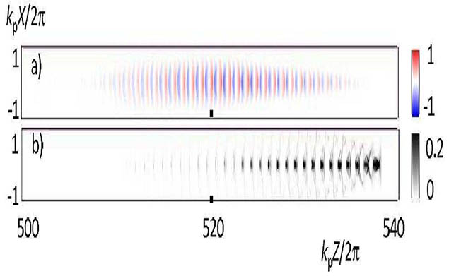
Figure 1. 3D PIC simulation results for a hard-cut half-Gaussian PDPWA driver beam. Panel (a) shows the accelerating wake field Ez , panel (b) shows the beam density distribution [17].
To achieve unprecedented electron beam energies in the TeV range, TeV proton beams from CERN’s Large Hadron Collider (LHC) have been proposed as a driver in a proton driver plasma wakefield acclerator (PDPWA) [14, 15]. In order to efficiently excite plasma waves that produce large accelerating gradients, the driver beam should be of order one plasma wavelength, $\lambda_p \equiv 2 \pi c / \omega_p$, where $\omega_p = \sqrt {4 \pi e^2 n_{p0} / m_e}$ is the plasma frequency, c is the speed of light, $n_{p0} \sim 10^{15} cm^{-3}$ is the density of the unperturbed plasma, $-e$ and $m_e$ are the electron charge and mass, respectively. However, for the plasma with $n_{p0} \sim 10^{15} cm^{-3}$ and wave-breaking field $E_{WB} = m c \omega_p / e \sim 1 GV/m$, the corresponding plasma wavelength $\lambda_p \sim 1 mm$ is much shorter than the r.m.s length $\sigma_z \sim 10 cm$ of the proton beams at the LHC. The proposed solution [16, 17] to this length scale mismatch is to rely on the modulation instability (MI) of a long proton bunch with $\sigma_z \gg \lambda_p$ . The MI perturbs the proton bunch density with the spatial period equal to $\lambda_p$ and resonantly excites the plasma wake, thereby producing a strong plasma wakefield. Panels (a) and (b) of Fig. 1 show snapshots of the axial accelerating gradient and beam density distributions for a PDPWA driver subjected to the MI [17]. To excite the MI, the instability must be initialized (seeded). One recently proposed seeding method is to ‘hard-cut’ the proton beam in the longitudinal direction [17] using a ‘dog-leg’ device [19]. Envisioned by the Shvets research group, another possible seeding method is to place a laser pulse in front of the proton beam and rely on its wakefield to excite the beam modulations [22]. The two instability seeding approaches are schematically shown in Fig. 2.
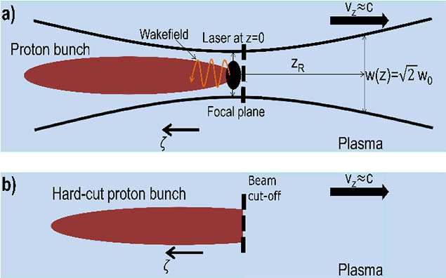
Figure 2. Schematic representation of laser (a) and hard-cut (b) modulation instability (MI) seeds. $\zeta = ct − z$ is the co-moving coordinate that measures the distance from the beam’s head located at the vertical dashed lines. Laser is shown in black, proton beam in red, and plasma in blue.
The initial growth stage of the MI, or ‘linear stage’, has been studied extensively in the past [17, 18] and is characterized by exponential growth of the longitudinal accelerating gradient and beam density. Growth during the linear stage occurs until a nonlinear saturation regime is reached in which these quantities cease growing and then begin to decrease. The particle-in-cell (PIC) simulated curves (see Ref. [22] for PIC description) of Fig. 3 demonstrate this phenomenon for several different initial r.m.s beam widths, $\sigma_r$. This effect has also been observed and discussed briefly in Ref. [21], but a more in-depth description of the MI’s saturation and subsequent decline is lacking.
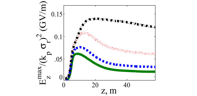
Figure 3. Growth, saturation, and decrease of maximal accelerating gradient produced by a PDPWA driver subjected to the modulation instability (MI) for several different initial beam sizes. Solid green, dashed blue, dotted red, and dashed/dotted black curves correspond to $k_p \sigma_r$ values of 1, .7, .35, and .1, respectively, which were calculated using the PIC described in Ref. [22]. This describes the evolution of these curves and calculates their peak accelerating gradient.
The Shvet’s research group is demonstrating that the screening produced by the plasma return current leads to the decay of the axial accelerating gradient produced by a PDWPA driver as it diffracts away. We accomplish this by working with the nonlinear envelope equation [17, 18, 20] that describes the evolution of a hard-cut proton beam’s r.m.s radius, which agrees reasonably well with PIC simulations throughout both the linear and nonlinear stages of the MI. Since this equation can only be solved numerically and does not reveal underlying effects, we use Fourier expansion techniques to derive a set of coupled, nonlinear evolution equations for the Fourier components of the beam’s r.m.s radius. This formalism enables us to directly study the effect of the phases and amplitudes of these Fourier components on the field behavior. We can also make estimates for the peak beam density and the peak accelerating gradient obtained during the MI using this formalism.
[1] T. Tajima and J. M. Dawson, Phys. Rev. Lett. 43, 267 (1979).
[2] P. Chen, J.M Dawson, R. W. Huff, and T. Katsouleas, Phys. Rev. Lett. 54, 693 (1985).
[3] J. Faure et al., Nature (London) 431, 541 (2004).
[4] C. G. R. Geddes et al., ibid. 431, 538 (2004).
[5] S. P. D. Mangles et al., ibid. 431, 535 (2004).
[6] W. P. Leemans et al., Nature Phys. 2, 696 (2006).
[7] S. Kneip et al., Phys. Rev. Lett. 103, 035002 (2009).
[8] X. Wang et al., Nature Comms., doi:10.1038/ncomms2988 (2012).
[9] I. Blumenfeld et al., Nature (London) 445, 741 (2007).
[10] Hogan, M.J. et al. Phys. Rev. Lett. 95, 054802 (2005).
[11] Hogan, M.J. et al. Phys. Plasmas, 7, 2241 (2000).
[12] Muggli, P. et al. Phys. Rev. Lett. 93, 014802 (2004).
[13] Ruth, R. D. et al. Part. Accel. 17, 171-189 (1985).
[14] A. Caldwell, K. Lotov, A. Pukhov, and F. Simon, Nature Phys. 5, 363 (2009).
[15] K. V. Lotov, Phys. Rev. ST Accel. Beams 13, 041301 (2010).
[16] K. Lotov, Proceedings of the 6th European Particle Acclerator Conf., Stockholm, Sweden, 1998, pp. 806 − 808.
[17] N. Kumar, A. Pukhov, K. Lotov, Phys. Rev. Lett. 104, 255003 (2010).
[18] C. B. Schroeder, C. Benedetti, E. Esarey, F. J. Gruner, and W. P. Leemans, Phys. Rev. Lett. 107, 145002 (2011).
[19] P. Muggli, V. Yakimenko, M. Babzien, E. Kallos, and K. P. Kusche, Phys. Rev. Lett. 101, 054801 (2008).
[20] E. P. Lee and R. K. Cooper, Part. Accel. 7, 83 (1976).
[21] K.V.Lotov, Phys. Plasmas, 18, 024501 (2011).
[22] C. Siemon, V. Khudik, A. Pukhov, G. Shvets, Phys. Plasmas 20, 103111 (2013).

